Glass fiber reinforcement is often chosen when a plastic part needs more stiffness, higher heat resistance, or better load-bearing performance. But the same reinforcement that improves structural capability can also make molding less forgiving. In practice, glass fiber reinforced plastic warpage is one of the most common issues engineers and molders face when a design moves from a neat datasheet target to real production, because fiber orientation, shrinkage imbalance, and cooling differences can pull the part out of shape in ways that standard unfilled plastics do not.
For projects where stiffness and dimensional control matter, the material decision often starts with the resin family and the reinforcement level, then quickly turns into processing and tooling questions. When a part needs a more tailored balance of rigidity, flow, and cosmetic quality, we often see buyers move toward glass fiber reinforced plastic compound options rather than assuming a standard grade will solve the issue. From a compounding perspective, Poly Maro looks at the full picture: base resin choice, fiber content, fiber length retention, additive package, shrinkage behavior, and how the material will actually behave in the customer’s mold, not just on paper.
Why Glass Fiber Reinforcement Is Used in Plastics
Glass fiber reinforcement is used because it changes the mechanical profile of a polymer in a very practical way. In many engineering plastics, the fiber phase raises stiffness, improves heat deflection performance, and reduces creep under load. That is why GF-reinforced materials are commonly selected for structural housings, brackets, supports, electrical components, and under-the-hood parts where the part must hold shape over time.
The value is straightforward: without reinforcement, some resins deform too easily under load or temperature. With reinforcement, the part can resist bending better and maintain tighter dimensional performance in service. That advantage is real, but it comes with trade-offs that affect flow, surface quality, and shrinkage behavior during molding.
For engineers, the key question is not whether glass fiber improves performance. It does. The real question is whether the application can tolerate the molding side effects that come with it. If a part has a visible exterior surface, long flow paths, asymmetrical geometry, or tight flatness requirements, the reinforcement can create more manufacturing risk than a buyer expects when comparing datasheets alone.
The Trade-Off: How Glass Fiber Changes Flow, Shrinkage, and Stress

Unfilled plastics tend to flow more uniformly. Once glass fiber is added, the melt becomes more directional. Fibers align with the flow path, the melt can become more viscous, and the part cools with different shrinkage behavior along and across the fiber direction. That means a molded article no longer shrinks evenly in all directions.
This is one reason why how to evaluate dimensional stability in plastics matters so much when evaluating reinforced grades. A part that looks acceptable immediately after demolding may still move during cooling, conditioning, or use. For procurement teams, this is important because dimensional instability often looks like a tooling problem, but the root cause may be a material-flow interaction.
Glass fibers also change how stress is distributed. In an unfilled part, stress can sometimes relax more uniformly. In a reinforced part, stress concentrates around knit lines, gates, corners, ribs, thickness transitions, and areas with uneven cooling. If the mold and process do not manage those stresses well, warpage becomes more pronounced and appearance defects become easier to see.
Why Warpage Happens More Easily in GF Reinforced Plastics
Warpage in GF-reinforced plastics usually comes from a combination of three effects: fiber orientation, anisotropic shrinkage, and uneven cooling. These three factors work together.
Fiber orientation
As the melt travels through the cavity, glass fibers align with flow. That alignment is useful for stiffness in one direction, but it creates nonuniform behavior across the part. The material does not shrink the same way in the flow direction and the transverse direction, so flat parts can curl, bow, or twist.
Anisotropic shrinkage
Because glass fibers restrict polymer shrinkage differently depending on direction, the part may contract unevenly after packing and cooling. If one section of the part has high fiber alignment and another has a different orientation pattern, the two regions pull against each other. The result may be edge lift, corner twist, or a dish-shaped panel that is difficult to control by process alone.
Uneven cooling
If the mold cools one area faster than another, the part solidifies under different stress states. In GF materials, those differences are amplified because the fiber network locks in orientation and shrinkage differences faster than a neat resin would. Thin-thick transitions, long flow lengths, and unbalanced cooling channels can all increase the chance of warpage.
In short, glass fiber reinforcement does not automatically cause warpage, but it makes the part far less forgiving of imbalance. The more geometry asymmetry and thermal imbalance the part has, the more likely the molded article will move after ejection.
Common Appearance Defects in Glass Fiber Reinforced Plastic Molding
Appearance defects are often the first sign that a GF-reinforced part is at risk. Even when the part meets mechanical targets, cosmetic issues can make it unsuitable for customer-facing or visible applications.
| Appearance issue | Typical cause | Why it is more common with GF materials |
|---|---|---|
| Fiber show | Fibers near the surface or poor surface replication | Fibers can protrude or telegraph through thin surface layers |
| Rough surface | High fiber content, mold texture interaction, or poor flow | Fibers interrupt the surface and reduce smoothness |
| Gloss inconsistency | Uneven orientation or cooling | Different regions reflect light differently after fiber alignment |
| Weld line visibility | Flow fronts meeting in the cavity | Fiber alignment around knit lines can make the line visible and weaker |
| Burn marks or flow marks | Poor venting, trapped air, or excessive shear | Reinforced melts often require tighter process control to avoid defects |
Weld lines deserve special attention because they are both a cosmetic and structural issue. In short glass fiber-reinforced parts, the meeting of two flow fronts can leave a visible seam and a weaker region if the fibers do not bridge the interface well. Research on weld lines and cosmetic/structural defects in short glass fiber-reinforced parts shows that microstructure and fiber orientation at the knit line can significantly affect performance, which is exactly why mold design and gate strategy matter so much.
For parts with exposed surfaces, buyers should not assume that a stronger material will still look clean. A resin that performs well in load-bearing applications may still require a paint, texture, or hidden location if visible fiber show is unacceptable.
Material Factors That Influence Warpage and Appearance
Material selection is not just about choosing “GF30” or “GF40.” Several formulation variables influence how the part will mold and whether warpage and appearance defects are manageable.
- Fiber content: Higher loading usually increases stiffness, but it can also raise viscosity, increase surface roughness, and make shrinkage more directional.
- Fiber length retention: Shortened fibers reduce reinforcement efficiency and can change flow behavior. The same nominal grade may behave differently if fiber breakage is inconsistent.
- Base resin: PA, PBT, PP, ABS, and other matrices respond differently to reinforcement. The resin controls moisture behavior, thermal stability, and processing window.
- Moisture: Hygroscopic resins can lose dimensional control if drying is insufficient. Moisture can also affect surface finish and cause splay or haze.
- Viscosity: A resin that is too viscous may fill poorly and increase orientation stress; a resin that flows too easily may not hold fiber distribution as intended.
- Additives: Heat stabilizers, impact modifiers, release agents, lubricants, and colorants can all influence flow, surface quality, and shrinkage.
When a project needs a nonstandard balance, the difference between a standard grade and a custom formulation can be decisive. Our experience matches what many buyers discover after trial runs: a default reinforced grade may work for stiffness, but fail on flatness, weld lines, or surface requirements. That is why custom plastic compound vs standard grade is not just a procurement question; it is a risk-control question for molded parts that need both performance and consistency.
Mold Design Factors That Can Make or Break the Result
Even a well-chosen material can warp if the mold design pushes the melt into an imbalanced pattern. In GF-reinforced parts, design choices influence fiber orientation more strongly than many teams expect.
Gate location and flow path
Gate placement largely determines how fibers orient. A gate that forces long, one-directional flow can create highly aligned fibers and large directional shrinkage. If the part is flat, the material may curl toward the orientation-dominant direction. Balanced gating and careful flow-path planning can reduce this risk.
Wall thickness uniformity
Thick-to-thin transitions encourage differential cooling and differential packing. In GF materials, those differences are magnified by fiber orientation and can produce surface sink, edge warp, and twist. Keeping wall thickness more uniform is one of the simplest ways to improve dimensional stability.
Cooling layout
Cooling should be balanced as much as the geometry allows. If one side of the cavity extracts heat much faster, the part will freeze unevenly and internal stress will be locked in. That stress later appears as warp or post-mold movement.
Venting
Insufficient venting traps air and can lead to burn marks, short shots, or local flow hesitation. That hesitation changes orientation and can produce cosmetic defects near the last-filled areas. Reinforced melts often need more deliberate vent design because they are less forgiving of trapped gas and shear hotspots.
Process Factors: The Small Changes That Have Big Effects
For GF-reinforced parts, process windows are often narrower than many molding teams expect. Small changes can alter orientation, packing efficiency, and surface appearance.
| Process variable | Too low | Too high | Typical effect on GF parts |
|---|---|---|---|
| Melt temperature | Poor flow, incomplete filling | Excess degradation, more flash risk | Affects fiber dispersion, surface, and weld line quality |
| Mold temperature | Frozen skin, high stress | Long cycle, overpacking risk | Influences gloss, shrinkage, and stress relaxation |
| Injection speed | Weak knit lines, poor fill | High shear, fiber breakage | Changes fiber orientation and surface appearance |
| Packing pressure | Sink and shrinkage | Overstress and flash | Controls post-fill shrink compensation |
| Cooling time | Part ejects before stabilization | Long cycles without added benefit | Affects warp release after demolding |
Drying is especially important when the matrix resin absorbs moisture. If drying is not controlled, the melt may foam slightly, splay, or lose surface quality, and the final part may also show unstable dimensions. For this reason, our team often recommends that customers document resin storage, dryer temperature, drying time, and transfer time before they start a trial run.
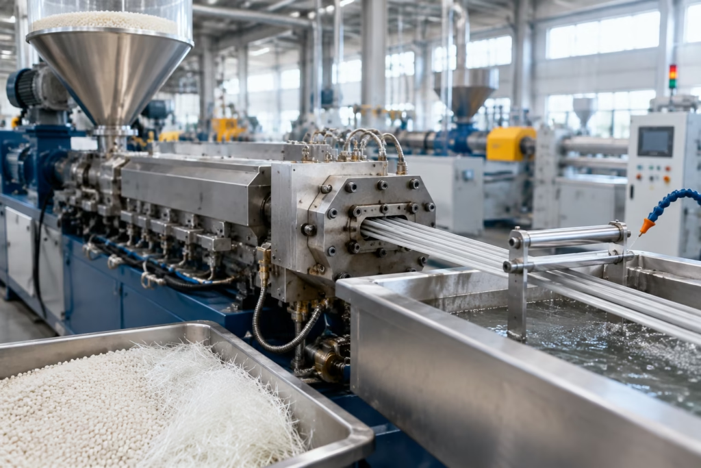
When the question is whether a problem comes from the grade or the setup, a structured validation plan helps more than guesswork. We recommend using a plastic material testing checklist for validation so that first samples are judged on dimensions, appearance, moisture handling, and molding stability rather than on one-off impressions from the press floor.
How to Reduce Glass Fiber Reinforced Plastic Warpage
Reducing warpage is usually a systems task, not a single adjustment. Material, mold, and process all need to work together.
- Balance the flow: Use gate placement and cavity design that avoid excessive directional orientation.
- Improve cooling uniformity: Reduce temperature differences across the part and across the cavity.
- Control packing: Apply enough packing pressure and time to offset shrinkage without over-stressing the part.
- Review wall transitions: Smooth abrupt thickness changes that create local sink or differential contraction.
- Optimize fiber content: Use the lowest reinforcement level that still meets the structural target.
- Adjust resin selection: Choose a matrix with a better balance of stiffness, flow, and shrinkage control for the application.
- Validate conditioning: Measure parts after appropriate conditioning, not only immediately after demolding.
One useful perspective is that warpage is often reduced more effectively by controlling where stress forms than by simply increasing clamping force or pressure. If the part design channels flow predictably and the cooling system is balanced, the reinforced resin can deliver the needed strength without excessive distortion.
How to Improve Surface Quality in GF-Reinforced Parts
Surface quality starts with the material choice, but it is heavily influenced by tool design and process control. If a part must look clean, the team should treat appearance as a design requirement, not a finish-line issue.
Choose the right resin grade for the visible surface. Some formulations are better at hiding fiber imprint and maintaining gloss. Manage fiber exposure by keeping flow and shear under control. Adjust mold finish carefully, because high texture may hide some imperfections while making others more obvious. Finally, tune the process so the melt does not over-shear at the gate or hesitate before the cavity is filled.
For material teams, it is helpful to ask whether cosmetic performance is truly needed on the same surface that carries structural load. In some applications, a hidden rib, internal bracket, or non-cosmetic side can absorb the reinforcement effects while a visible surface uses a different material strategy. That is often more realistic than forcing one reinforced grade to satisfy every requirement at once.
At Poly Maro, this is the kind of trade-off we evaluate when we develop or adjust a compound: does the customer need stiffness first, appearance first, or a balanced compromise? The answer determines reinforcement level, base resin, additive package, and the way the grade should be validated in actual molding.
When GF Reinforcement Is the Right Choice and When It Is Not
Glass fiber reinforcement is a strong choice when the part must hold shape under load, resist heat, or improve structural reliability. It is especially useful for internal structural components, industrial housings, brackets, electrical supports, automotive brackets, and molded components that are not highly cosmetic.
It may be the wrong choice when the part has a highly visible Class-A surface, very tight flatness requirements across a large panel, or complex geometry that already creates uneven flow. In those cases, the cost of chasing warpage and appearance defects can exceed the benefit of added stiffness. A different resin, a lower fiber content, or an alternative modification strategy may give a better total result.
This is also where buyer expectations matter. A reinforced grade may have a higher material cost, but the total cost of molding can still be lower if it reduces creep, supports lighter designs, or prevents in-service deformation. On the other hand, if the project spends too much time and scrap chasing appearance, the hidden cost rises quickly. That is why material choice should always be tied to actual part requirements, not just nominal performance numbers.
Sample Validation and Production Checklist for GF Reinforced Parts
Before moving from trial to mass production, the team should validate both dimensional behavior and appearance under conditions that match real use. We recommend treating sample approval as a structured technical review.
- Confirm the dried resin condition before molding.
- Inspect first shots for short fill, flow marks, burn marks, and knit lines.
- Measure critical dimensions immediately after molding and again after conditioning.
- Check flatness, twist, bow, and edge lift on the actual part geometry.
- Evaluate surface roughness, gloss consistency, and fiber show under the intended lighting.
- Compare multiple cavity shots if the tool is multi-cavity to detect imbalance.
- Review process settings that were used for the approved sample and lock them down.
- Confirm packaging, batch traceability, MOQ, and lead time before release to production.
Where dimension control is critical, use standardized measurement methods rather than visual judgment alone. Formal dimensional testing matters because apparent flatness after demolding does not always predict long-term stability. A useful reference point is ASTM’s standard methods for measuring dimensional stability and shrinkage, which reinforces the idea that warpage-related change should be measured consistently under defined conditions.
From our side as a manufacturer, the most successful projects are the ones where the customer shares drawings, appearance criteria, target cycle time, and any post-mold conditioning expectations early. That allows us to narrow the compound window before full-scale sampling begins.
Practical Selection and Development Tips from a Plastic Pellet Manufacturer Perspective
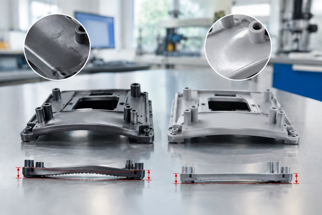
In material development, the strongest result usually comes from aligning the grade to the part instead of forcing the part to accept a standard grade. If a design has a long flow path, a visible surface, and strict flatness, the compound may need different reinforcement content or a different base resin than the one used for a hidden structural bracket. If the part needs stiffness and heat resistance but can tolerate moderate surface fiber show, a more conventional GF grade may be acceptable.
We also find that procurement teams benefit from asking suppliers about processing behavior, not just mechanical properties. Questions about drying window, recommended melt temperature, gate sensitivity, and batch consistency often reveal more about real-world risk than a single data-sheet number. When a supplier can explain how the grade behaves in the mold and how it was tuned for the application, the project is usually in a much better position.
That is where custom compounding becomes useful. If the project needs lower warp, better surface, or improved balance between stiffness and flow, custom plastic compounding support can help adjust the formulation around the part requirement rather than around a generic catalog target. In many cases, that is the difference between a part that merely molds and a part that stays stable in production.
For teams sourcing materials, the final decision should always balance performance, processing stability, cosmetic needs, and commercial fit. A grade that solves one problem but creates two others is rarely a good choice. The more clearly the application is defined, the easier it becomes to choose a resin system that delivers predictable molding and consistent output.
Conclusion
Glass fiber reinforcement is valuable because it boosts stiffness, heat resistance, and dimensional support, but those gains come with a cost: more directional shrinkage, more stress sensitivity, and more visible appearance risk. That is why glass fiber reinforced plastic warpage is not just a molding nuisance; it is a sign that material selection, mold design, and process control need to be aligned more carefully.
When engineers and buyers understand the trade-off early, they can make better decisions about reinforcement level, resin base, gate strategy, cooling balance, and validation testing. In our experience, the best outcomes come from treating the compound as part of the part design, not as a late-stage substitution. That approach reduces scrap, shortens trial cycles, and improves the chance of stable production.
FAQs
Why do glass fiber reinforced plastics warp more than unfilled plastics?
They warp more easily because the fibers align with flow, which creates directional shrinkage and uneven stress. If the mold cools unevenly or the part has an unbalanced geometry, those internal differences can pull the part out of shape after demolding.
Does a higher glass fiber content always reduce warpage?
No. More fiber can improve stiffness, but it can also increase flow resistance, surface roughness, and anisotropic shrinkage. In some parts, a lower fiber content with a better resin balance gives a flatter and more usable result.
What causes visible fiber show on the surface?
Fiber show usually comes from fibers near the surface, high shear, thin cover layers, or tooling that does not hide the reinforcement well. It is more noticeable in reinforced materials because fibers can telegraph through the surface finish during molding and cooling.
How can weld lines be reduced in GF-reinforced parts?
Weld lines can often be improved by adjusting gate location, balancing flow, raising melt or mold temperature within the safe window, and improving venting. If a knit line is unavoidable, the team should verify both the appearance and the mechanical performance at that location.
Should warpage be checked only right after molding?
No. Parts should be checked after conditioning or after they have had time to stabilize, especially if the base resin absorbs moisture or continues to release stress after ejection. Immediate inspection is useful, but it does not always show the final shape.
When should a buyer ask for a custom compound instead of a standard grade?
A custom compound makes sense when the standard grade solves one requirement but creates issues with warpage, appearance, moisture response, or processing stability. If the project has tight dimensional or cosmetic limits, a custom formulation often gives a better overall fit.